Connecting the BME280 sensor to ESP8266 and creating weather station with VizIoT
This article is current as of May 28, 2024, operating system Mac OS.
Introducing BME280 sensor
We went through how to program the ESP8266 module to control the on-board LED as well as remotely access it in the previous block.
This instruction will take us a little further, where we will realize the possibility of creating a home weather station based on a microcontroller ESP8266 and a temperature, humidity and pressure sensor connected to it. For connection we will need the experience from the previous article, BME280 sensor, connecting wires to connect to the pins of the module and the sensor.
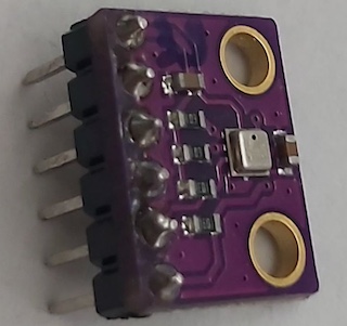
View of sensor:
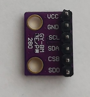
| Connection* | Плата ESP8266 | Датчик BME280 |
|---|---|---|
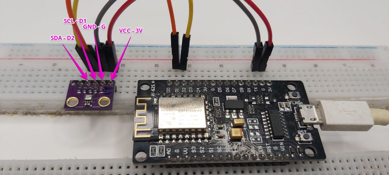
| power connection | G | GND |
| power connection | 3V | VCC |
| control | D1 | SCL |
| control | D2 | SDA |
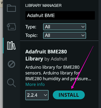
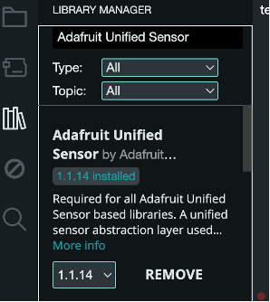
Installing the required libraries
Devices are connected, the Adafruit BME280 Library must be installed for the code to work correctly:
I2C address for BME280 sensor
To work with BME280 sensor it is necessary to know its address, as it works on I2C communication protocol, which allows to connect many different sensors with different addresses.
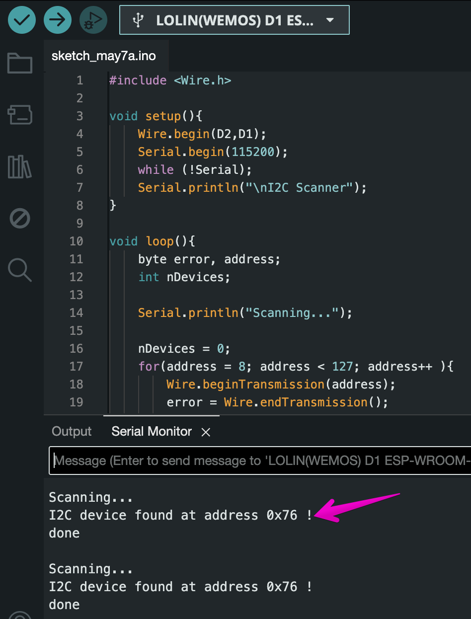
Below is provided a sketch to find connected sensors via I2C protocol on pins D1 and D2.
Copy, paste, load the following code into the compiler:
#include <Wire.h>

void setup(){
    Wire.begin(D2,D1);
    Serial.begin(115200);
    while (!Serial);
    Serial.println("\nI2C Scanner");
}

void loop(){
    byte error, address;
    int nDevices;

    Serial.println("Scanning...");

    nDevices = 0;
    for(address = 8; address < 127; address++ ){
        Wire.beginTransmission(address);
        error = Wire.endTransmission();

        if (error == 0){
            Serial.print("I2C device found at address 0x");
            if (address<16)
                Serial.print("0");
            Serial.print(address,HEX);
            Serial.println(" !");

            nDevices++;
        }
        else if (error==4) {
            Serial.print("Unknow error at address 0x");
            if (address<16)
                Serial.print("0");
            Serial.println(address,HEX);
        }
    }
    if (nDevices == 0)
        Serial.println("No I2C devices found\n");
    else
        Serial.println("done\n");

    delay(5000);
}
Open the console (Serial Monitor) to view the address of the sensor connected to the ESP8266 module. The address should be displayed if the connection is made correctly:
- incorrectly connected pins to the board legs
- the corresponding port is not selected
- the appropriate board name is not selected.
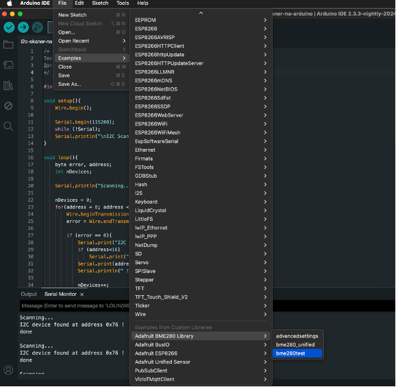
Receiving data from the BME280
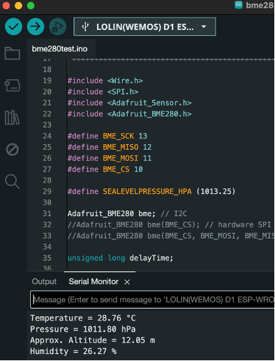
After the device address is found and the libraries are installed, we can go to file -> examples -> adafruit BME280 Library -> bme280test and install the sketch for BME280 module.
Serial.begin(9600); and change the serial baud rate from 9600 to 115200 baud, and in status = bme.begin(); we pass the address we got from the previous scanner sketch. Now it should look like this: status = bme.begin(0x76);
#include <Wire.h>
#include <SPI.h>
#include <Adafruit_Sensor.h>
#include <Adafruit_BME280.h>
#define BME_SCK 13
#define BME_MISO 12
#define BME_MOSI 11
#define BME_CS 10
#define SEALEVELPRESSURE_HPA (1013.25)
Adafruit_BME280 bme; // I2C
//Adafruit_BME280 bme(BME_CS); // hardware SPI
//Adafruit_BME280 bme(BME_CS, BME_MOSI, BME_MISO, BME_SCK); // software SPI
unsigned long delayTime;
void setup() {
Serial.begin(115200);
while(!Serial); // time to get serial running
Serial.println(F("BME280 test"));
unsigned status;
// default settings
status = bme.begin(0x76);
// You can also pass in a Wire library object like &Wire2
// status = bme.begin(0x76, &Wire2)
if (!status) {
Serial.println("Could not find a valid BME280 sensor, check wiring, address, sensor ID!");
Serial.print("SensorID was: 0x"); Serial.println(bme.sensorID(),16);
Serial.print(" ID of 0xFF probably means a bad address, a BMP 180 or BMP 085\n");
Serial.print(" ID of 0x56-0x58 represents a BMP 280,\n");
Serial.print(" ID of 0x60 represents a BME 280.\n");
Serial.print(" ID of 0x61 represents a BME 680.\n");
while (1) delay(10);
}
Serial.println("-- Default Test --");
delayTime = 1000;
Serial.println();
}
void loop() {
printValues();
delay(delayTime);
}
void printValues() {
Serial.print("Temperature = ");
Serial.print(bme.readTemperature());
Serial.println(" °C");
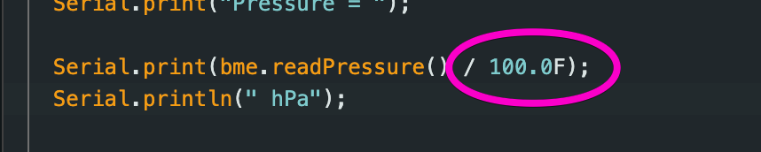
Serial.print("Pressure = ");
Serial.print(bme.readPressure() / 100.0F);
Serial.println(" hPa");
Serial.print("Approx. Altitude = ");
Serial.print(bme.readAltitude(SEALEVELPRESSURE_HPA));
Serial.println(" m");
Serial.print("Humidity = ");
Serial.print(bme.readHumidity());
Serial.println(" %");
Serial.println();
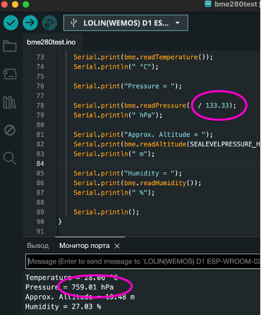
}then update sketch by pressing upload, open the port monitor where you can see the temperature, humidity, pressure and approximate altitude readings.
Introduction to VizIoT
In the next section, we will explore the features of the VizIoT website. Why do we need this? In the previous article, we connected the BME280 sensor and saw the temperature, humidity, and atmospheric pressure readings in the console. However, this method of displaying information is inconvenient and impractical. To make it easier to view and analyze the data from our weather station, we will use the VizIoT service. By using VizIoT, we get:
- access to cloud data storage,
- tools for data visualization,
- the ability to share the weather station with friends,
- notifications in Telegram,
- and even remote control of our weather station.
This platform is not only useful for home needs but can also be a valuable tool for business or other applications. It can be used to display and process data on:
- soil temperature and humidity in fields,
- climatic conditions in greenhouses and farms,
- resource consumption (electricity, water, gas),
- the condition of servers and electrical appliances in production facilities, and much more. You can track data using your custom dashboards, analyze information for any period, and manage access to the data. The diagnostics section allows you to analyze all parameters transmitted by devices over a certain period.
The system supports connecting multiple devices through MQTT and HTTP protocols. Future plans for VizIoT include expanding its capabilities, adding support for the LoRaWAN protocol, and creating new widgets such as weather, manipulators (switch buttons, sliders), and audio/video players. Functionality for processing geographic data will also be added, for example, displaying GPS data points and sensor movement tracks.
Sending Data from BME280 to the VizIoT Server
Transmitting Data from BME280 to VizIoT Server
We covered how to connect the BME280 sensor to ESP8266 above, now let's move to the next stage where the connected sensor will transmit temperature and humidity readings to a remote server, from which we'll display the parameters on screen. For this, we need to visit app.VizIoT.com, register or log into your account.
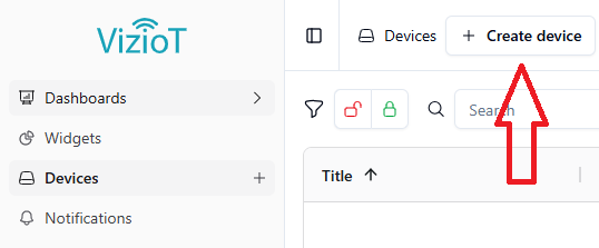
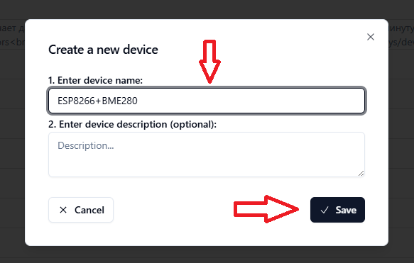
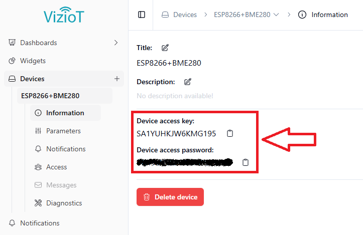
On the "Devices" page, create a new device named ESP8266+BME280 (the name is optional), after which you'll receive an access key and password for this device.
We'll use the obtained data (key and password) in the following sketch, which can be copied and pasted into Arduino IDE:
#include <ESP8266WiFi.h>
#include <ESP8266HTTPClient.h>
#include <WiFiClient.h>
#include <Wire.h>
#include <Adafruit_Sensor.h>
#include <Adafruit_BME280.h>

// WiFi settings
const char* ssid = "YOUR_WIFI_SSID";          // Replace with your WiFi network name
const char* password = "YOUR_WIFI_PASSWORD";  // Replace with your WiFi password

// VizIoT device key and password (can be found in device settings)
const String VizIoT_Device_key = "YOUR_VIZIOT_DEVICE_KEY";    // Replace with your VizIoT device key
const String VizIoT_Device_pass = "YOUR_VIZIOT_DEVICE_PASS";  // Replace with your VizIoT device password

// Parameters for sending data to VizIoT.com
const String serverURL = "http://VizIoT.com/update";

// BME280 sensor initialization
Adafruit_BME280 bme;

WiFiClient wifiClient;
HTTPClient http;

void setup() {
  Serial.begin(115200);
  Serial.println("Starting ESP8266...");

  // Initialize BME280 sensor
  Wire.begin();
  if (!bme.begin(0x76)) {
    Serial.println("BME280 sensor not found!");
  } else {
    Serial.println("BME280 sensor connected");
  }

  // Connect to WiFi
  WiFi.begin(ssid, password);
  Serial.print("Connecting to WiFi");
  while (WiFi.status() != WL_CONNECTED) {
    delay(500);
    Serial.print(".");
  }
  Serial.println();
  Serial.println("WiFi connected!");
}

void loop() {
  // Read data from BME280 sensor
  float temperature = bme.readTemperature();
  float humidity = bme.readHumidity();

  // Output data to serial monitor
  Serial.print("Temperature: ");
  Serial.print(temperature);
  Serial.print("°C, Humidity: ");
  Serial.print(humidity);
  Serial.println("%");

  // Build URL for sending data
  String url = serverURL + "?key=" + VizIoT_Device_key + "&pass=" + VizIoT_Device_pass + "&temp=" + String(temperature, 2) + "&hum=" + String(humidity, 2);

  // Send data
  http.begin(wifiClient, url);
  int httpCode = http.GET();

  if (httpCode > 0) {
    String response = http.getString();
    if (response == "OK") {
      Serial.println("Data successfully sent");
    } else {
      Serial.println("Error occurred while sending data");
      Serial.println("Server response: " + response);
    }
  } else {
    Serial.println("Error occurred while sending data");
    Serial.println("Error code: " + String(httpCode));
  }

  http.end();

  delay(20000);  // Send data every 20 seconds
}
After uploading the sketch to the ESP8266 module, the following information should appear in the console (serial monitor):
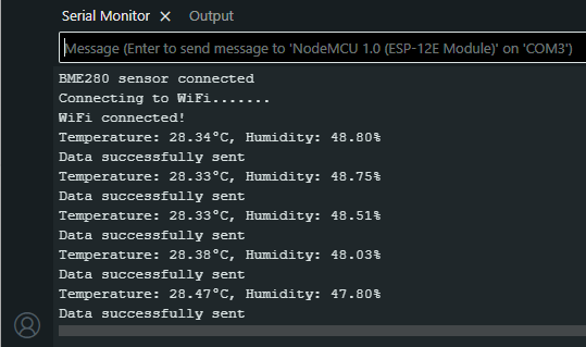
In the screenshot above, we can see that BME280 is successfully connected to the ESP8266 board and transmitting data to the VizIoT server.
In case of no data transmission and errors found in the console, you need to make sure that you've correctly entered the WiFi network name and password, as well as the device key and password from the VizIoT website. Also ensure that communication with the BME280 sensor is established via the I2C interface.
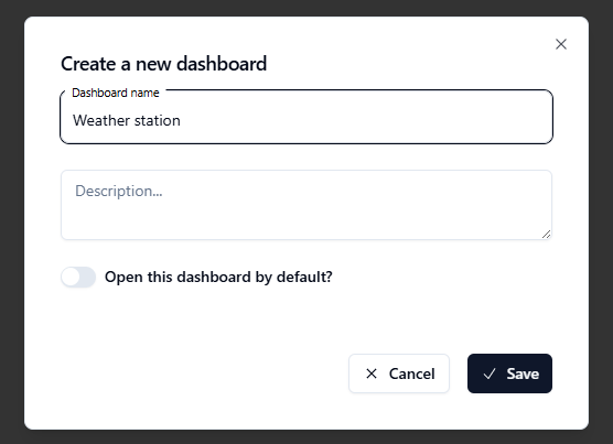
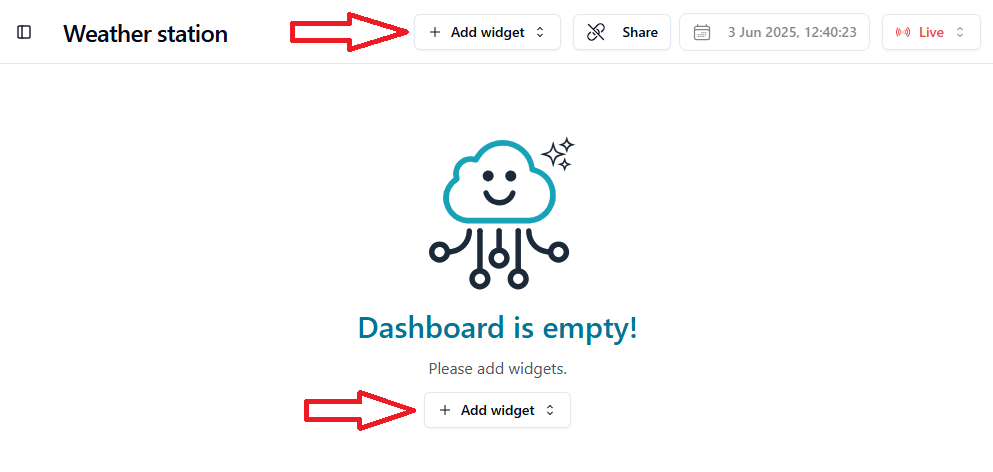
The next step on the VizIoT website is to open the "Dashboards" page and create a dashboard named "Weather Station":
In the created dashboard, we add widgets. Click the "Add Widget" button, then click "Create Widget".
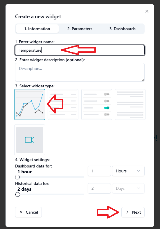
In the form that appears, enter the widget name "Temperature", select the widget type "Charts", and proceed to the next step "Adding Widget Parameters".
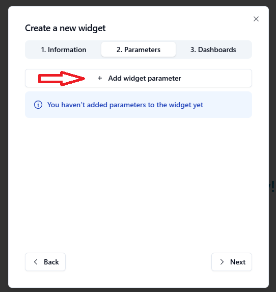
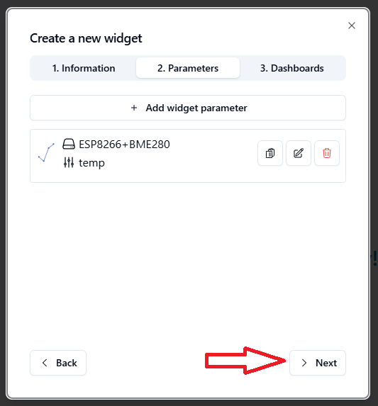
A widget can have multiple parameters, but in this case we only need one parameter, namely the value of the temp parameter from the ESP8266+BME280 device.
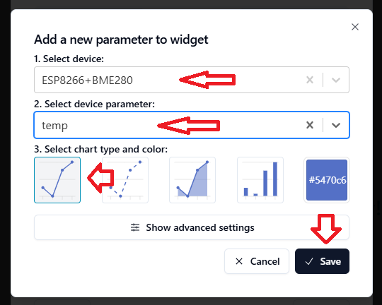
Let's add it. First, you need to select the device, then the device parameter and how to display it - I chose the default option. You can choose whatever you want and assign it any color. I also recommend checking the additional settings, there's a lot of interesting stuff there. Once you've made your selection, click "Save".
A parameter has appeared, then we just need to go to the next tab for selecting Dashboards where we want to add the widget.
By default, our dashboard is already selected, we just need to click the "Save" button.
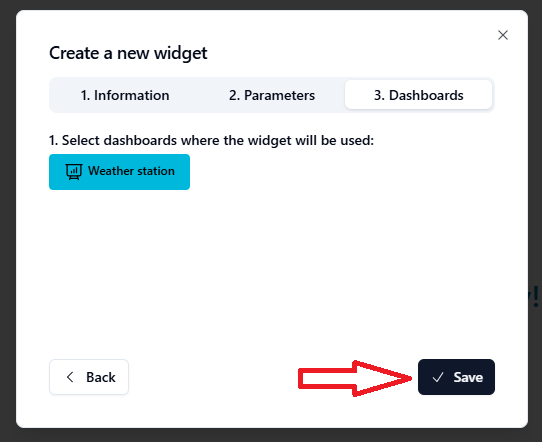
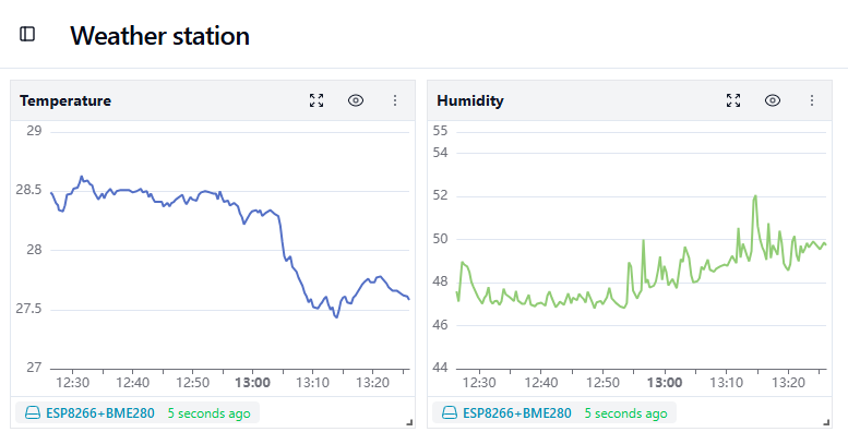
And our widget will appear on the "Weather Station" dashboard.
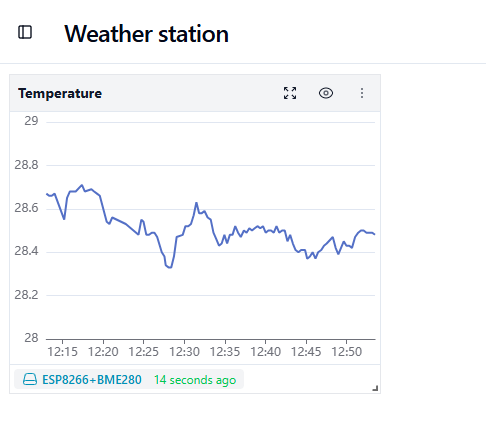
Similarly to temperature, add another widget but with humidity readings. As a result, you'll see such a dashboard with two widgets.