Remote Control of ESP8266
This algorithm is current as of 25.04.2024, operating system Mac OS.
Introduction
Before we dive into the details of setting up and using remote control for the ESP8266, let's watch a short video that demonstrates the final result. This will give you an idea of what we will be creating and how it works in real conditions.
Description
After watching the video, you may have a few questions. In this article, we will take a detailed look at how to create and set up remote control for the ESP8266 using the VizIoT platform. We will go through all the steps, from the necessary components to the final settings and testing.
In previous sections, we covered how to program the ESP8266 module to control the onboard LED, connect the BME280 sensor, and connect the microcontroller to the Wi-Fi network:
In this article, in less than 20 minutes, we will learn how to remotely control an LED, but we will not stop there. We will also connect and control an electrical appliance from a remote server by pressing a button on a computer or phone screen. In the end, we will build a physical prototype for controlling various devices at home, at the cottage, or in the enterprise using a remote server connection.
1. Registering on the VizIoT website
1.1 Register on VizIoT.
1.2 On the "devices" tab, create a new device named ESP8266+BME280 (name is optional), then obtain the access key and password for this device.
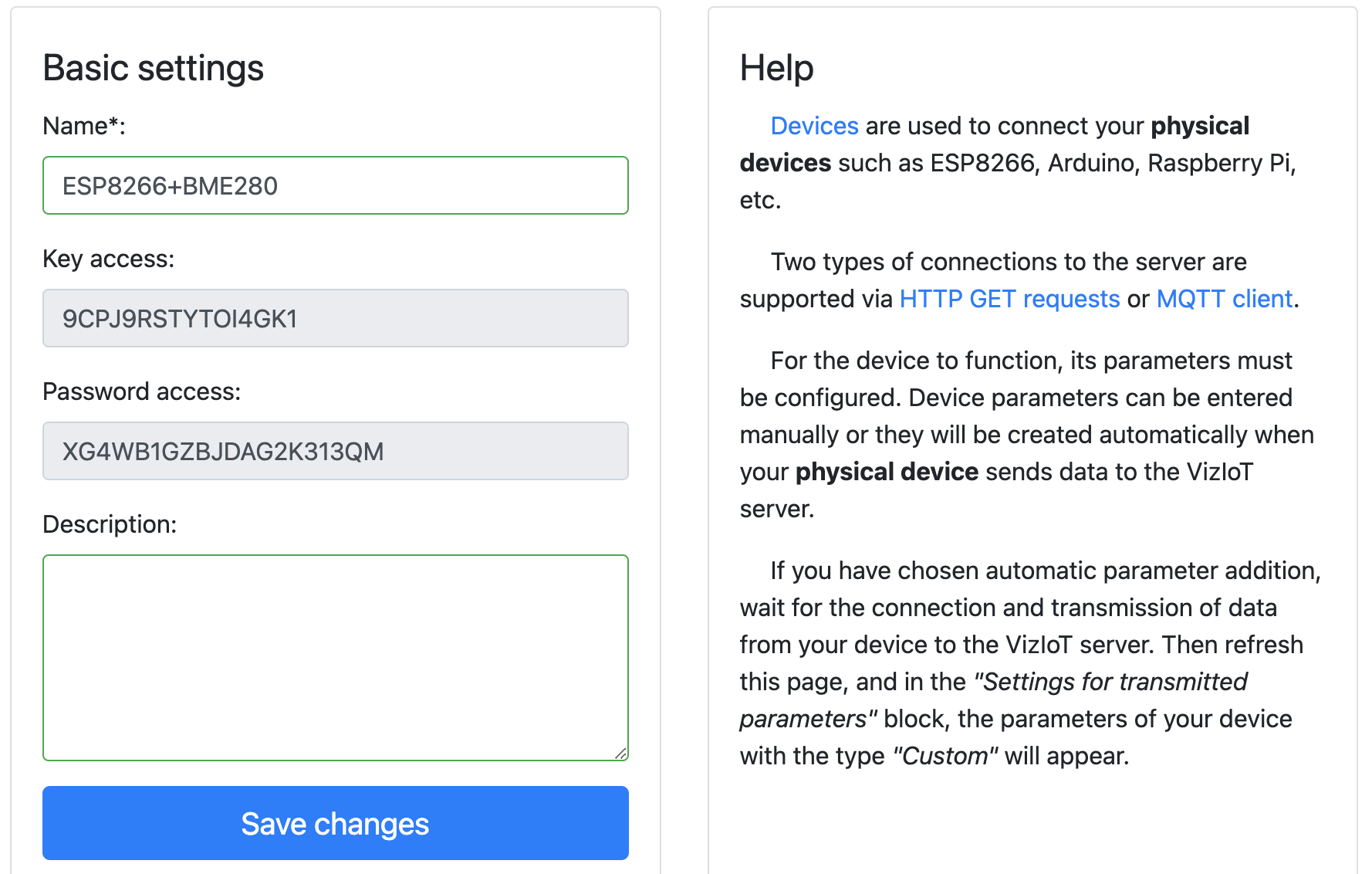
1.3 The obtained data (key and password) will be used in the following sketch (standard ESP8266 LED control example), which can be copied and pasted into the Arduino IDE:
#include <ESP8266WiFi.h>
#include <VizIoTMqttClient.h>
#include <ArduinoJson.h>
#include <Ticker.h>

// SSID and password to connect to Wi-Fi
const char* WIFI_SSID = "your_wifi_ssid";
const char* WIFI_PASSWORD = "your_wifi_password";

// Device key and password
const char* VIZIOT_DEVICE_KEY = "your_16_char_device_key";
const char* VIZIOT_DEVICE_PASS = "your_20_char_device_pass";

// Create MQTT client
VizIoTMqttClient mqttClient(VIZIOT_DEVICE_KEY, VIZIOT_DEVICE_PASS);

// LED pin
#define LED_ESP D4
// LED state
bool ledState = false;

// Timer to send data to the VizIoT MQTT broker
Ticker sender;
bool isSendDataToServer = false;
void SendDataToServer() {
  isSendDataToServer = true;
}
#define INTERVAL_SEND_DATA 300  // Send data every 5 minutes (5*60=300)

// Function to send data to VizIoT MQTT broker
void sendPacketToVizIoT() {
  DynamicJsonDocument doc(256);
  JsonObject obj = doc.to<JsonObject>();
  obj["led"] = ledState ? 1 : 0;
  obj["rssi"] = WiFi.RSSI();

  String jsonStr;
  serializeJson(doc, jsonStr);

  if (mqttClient.publishJson(jsonStr.c_str())) {
    Serial.println("Published JSON: " + jsonStr);
  } else {
    Serial.println("Failed to publish JSON");
  }
}

// Callback for parameters received from the VizIoT MQTT broker
void onParameterReceived(const char* paramName, const char* value) {
  Serial.print("Received parameter: ");
  Serial.print(paramName);
  Serial.print(" = ");
  Serial.println(value);

  if (strcmp(paramName, "led") == 0) {
    bool newState = (strcmp(value, "1") == 0);
    ledState = newState;
    digitalWrite(LED_ESP, ledState ? LOW : HIGH);  // Turn ON = LOW
    Serial.print("LED state updated to: ");
    Serial.println(ledState ? "ON" : "OFF");
    sendPacketToVizIoT();
  }
}

// Function to connect to Wi-Fi
void setup_wifi() {
  WiFi.begin(WIFI_SSID, WIFI_PASSWORD);
  Serial.print("Connecting to Wi-Fi...");
  while (WiFi.status() != WL_CONNECTED) {
    delay(1000);
    Serial.print(".");
  }
  Serial.println("Connected to Wi-Fi");
}

void setup() {
  // Enable output to Serial Monitor
  Serial.begin(115200);

  // Allow control of the LED
  pinMode(LED_ESP, OUTPUT);
  digitalWrite(LED_ESP, HIGH);  // LED off

  // Connect to Wi-Fi
  setup_wifi();

  // Start MQTT client and set callback for incoming messages
  mqttClient.begin();
  mqttClient.setParameterCallback(onParameterReceived);

  // Create a data sending event every INTERVAL_SEND_DATA seconds
  sender.attach(INTERVAL_SEND_DATA, SendDataToServer);

  // Send data as soon as we connect to the broker
  SendDataToServer();
}

void loop() {
  // Check Wi-Fi connection
  if (WiFi.status() != WL_CONNECTED) {
    WiFi.reconnect();
    delay(1000);
    return;
  }

  // Handle incoming messages and maintain MQTT connection
  mqttClient.poll();
  if (!mqttClient.isConnected()) {
    mqttClient.reconnect();
  }

  // Send data to the server every 5 minutes
  if (isSendDataToServer) {
    isSendDataToServer = false;
    sendPacketToVizIoT();
  }

  delay(100);
}
2. Installing libraries in Arduino IDE
To work with the module, you need to install 3 libraries:
2.1 Options for installing the VizIoTMqttClient library in Arduino IDE: Check if the VizIoTMqttClient library is present in the Arduino IDE catalog by typing VizIoTMqttClient in the search bar:
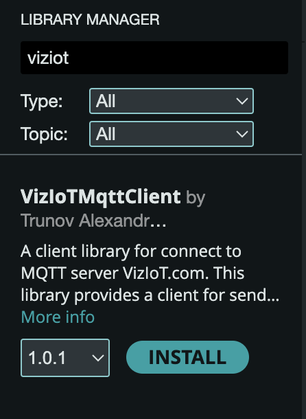
ArduinoJson and for Ticker.
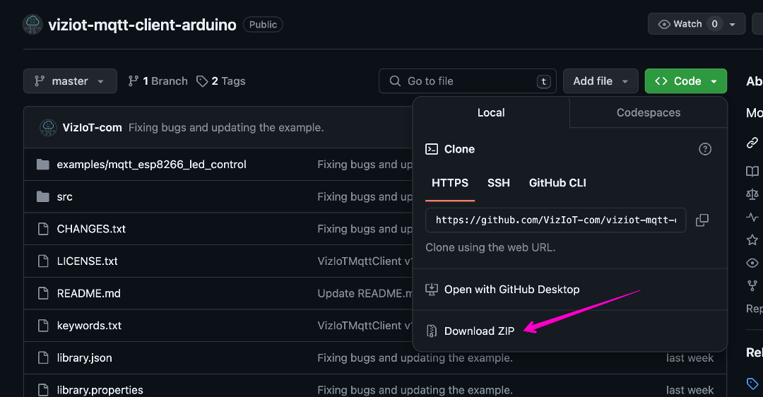
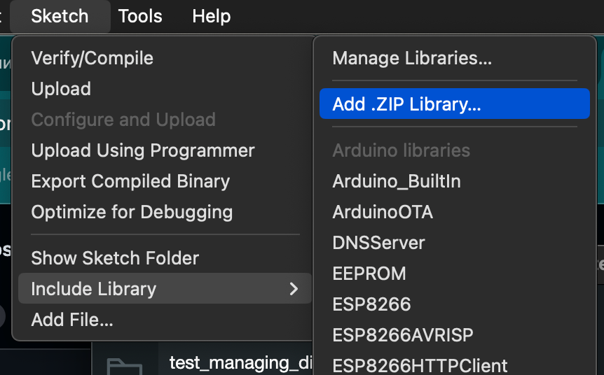
2.2 If this library is not in the Arduino IDE catalog, go to the link VizIoTMqttClient, in the open github window, open Code, where select Download ZIP, download it to the downloads directory or any other directory you can access later, knowing the path.
3. Setting up dashboard and widgets
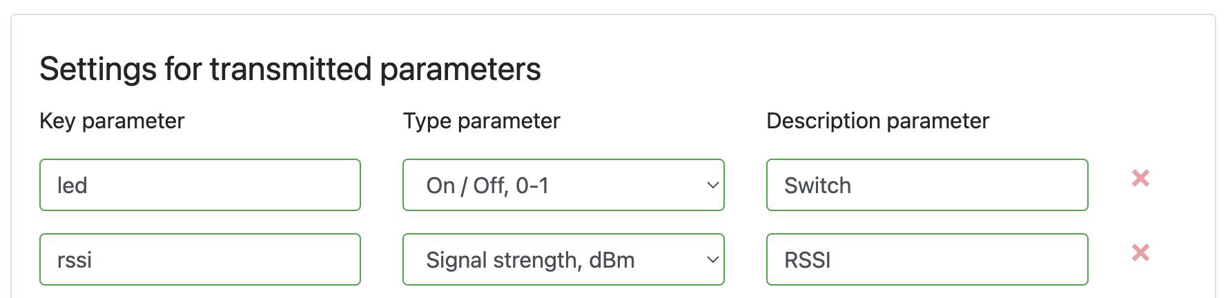
3.1 The sketch is downloaded, libraries are installed, now connect the ESP8266 to the computer, upload the code, and go to the device settings (block Settings of transmitted parameters) i.e., continue from item 1.2.
Set the parameters that will be transmitted to the server:
- RSSI - the parameter key for transmitting Wi-Fi signal strength data, parameter type: “Signal strength, dBm”.
- led - the parameter key for transmitting LED control data, parameter type: “On/off, 0-1”.
- In the “Parameter description” field for led, you can write “Switch,” this label will appear on the widget.
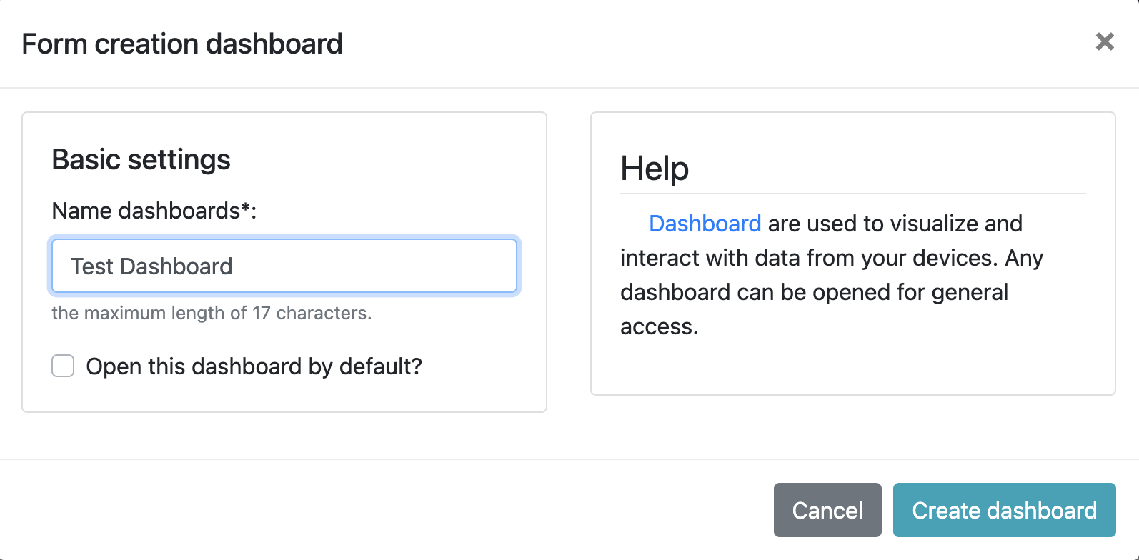
3.2 Save it, then go to dashboard and create a new panel. Click Create dashboard and name it, for example, Test Dashboard:
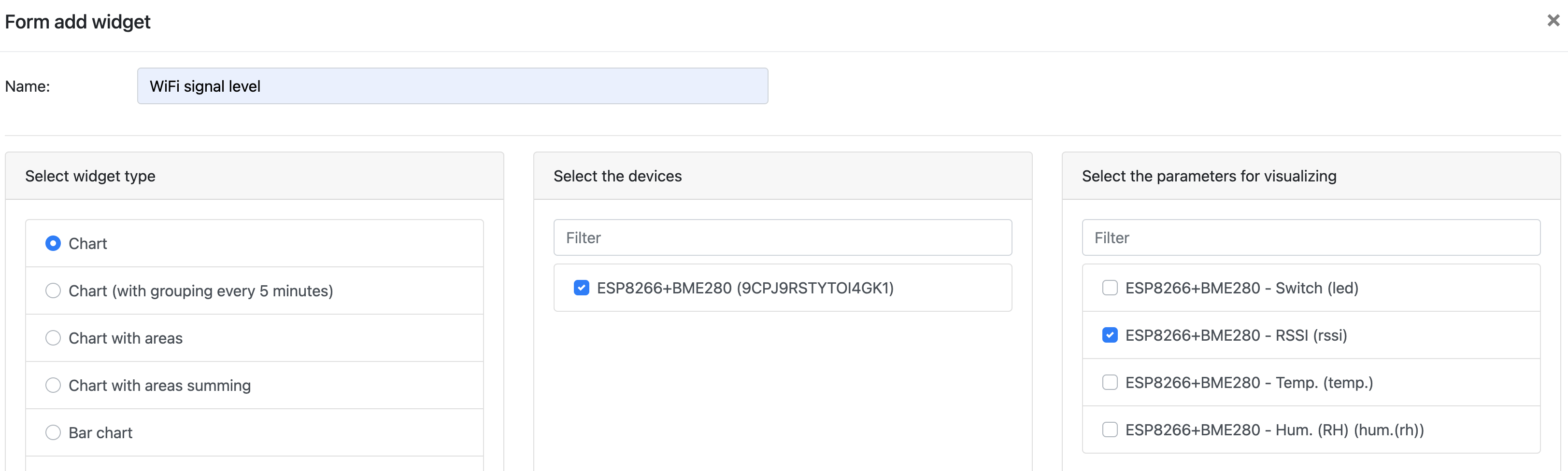
3.3 Create a widget for the dashboard: enter a name, for example, Wi-Fi signal level, select the widget type Chart, then select the device and parameters for visualization, in this case rssi.
At the bottom right is the "Add widget" button, click on it.
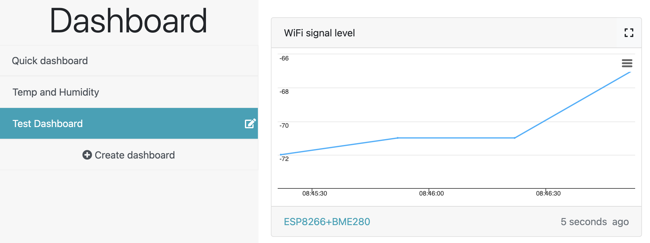
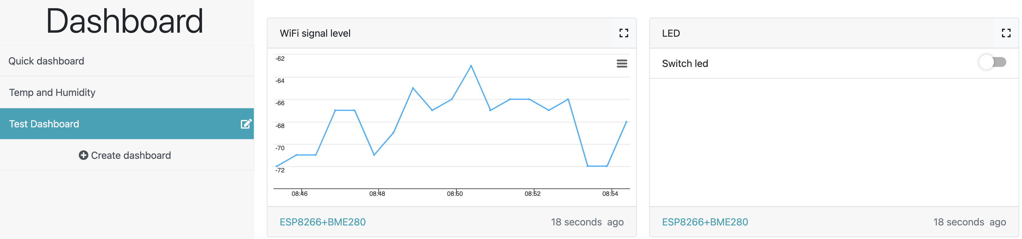
3.4 As a result, we get a widget displaying an online graph of the Wi-Fi signal
+ in the lower right corner and create a widget to control the LED, set the name, select the Switches parameters, then select the device and parameters for control
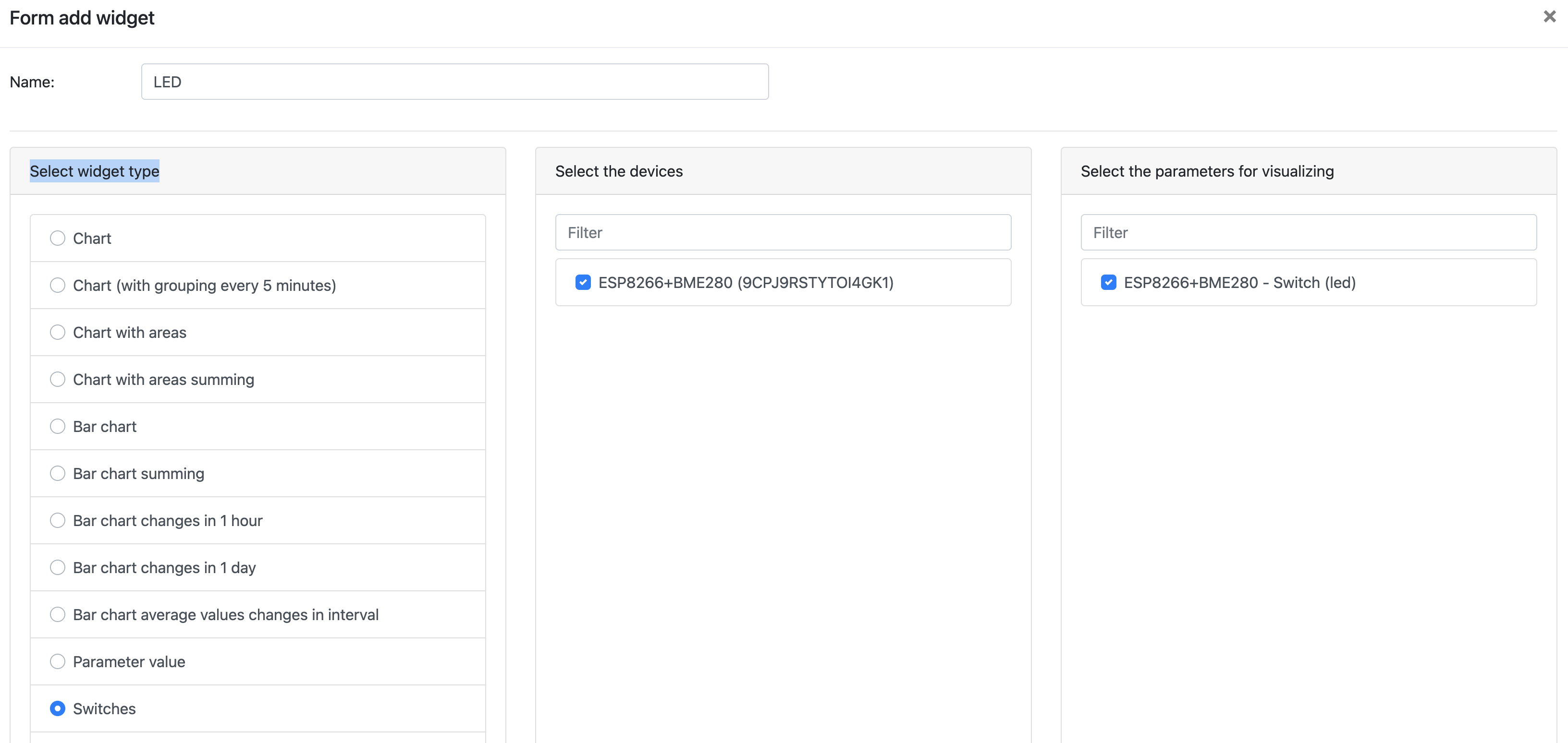
3.6 After that, two widgets will appear on the screen on the Test panel:
4. Remote control of devices
Before you start remotely controlling devices, let's build a primitive circuit. For example, connect an external LED to pin D0, making a small adjustment to the sketch used above, so it will blink using the same button as in item 3.6. To do this, change the pin address in the define LED_ESP constant - replace D4 with D0. And also change the values of HIGH and LOW in the digitalWrite function for the digital input/output (pin):
#define LED_ESP D0

//.........

digitalWrite(LED_ESP, ledState ? HIGH : LOW);  // Turn ON = HIGH

//.........

digitalWrite(LED_ESP, LOW);  // LED off
And install the sketch:
#include <ESP8266WiFi.h>
#include <VizIoTMqttClient.h>
#include <ArduinoJson.h>
#include <Ticker.h>

// SSID and password to connect to Wi-Fi
const char* WIFI_SSID = "your_wifi_ssid";
const char* WIFI_PASSWORD = "your_wifi_password";

// Device key and password
const char* VIZIOT_DEVICE_KEY = "your_16_char_device_key";
const char* VIZIOT_DEVICE_PASS = "your_20_char_device_pass";

// Create MQTT client
VizIoTMqttClient mqttClient(VIZIOT_DEVICE_KEY, VIZIOT_DEVICE_PASS);

// LED pin
#define LED_ESP D0
// LED state
bool ledState = false;

// Timer to send data to the VizIoT MQTT broker
Ticker sender;
bool isSendDataToServer = false;
void SendDataToServer() {
  isSendDataToServer = true;
}
#define INTERVAL_SEND_DATA 300  // Send data every 5 minutes (5*60=300)

// Function to send data to VizIoT MQTT broker
void sendPacketToVizIoT() {
  DynamicJsonDocument doc(256);
  JsonObject obj = doc.to<JsonObject>();
  obj["led"] = ledState ? 1 : 0;
  obj["rssi"] = WiFi.RSSI();

  String jsonStr;
  serializeJson(doc, jsonStr);

  if (mqttClient.publishJson(jsonStr.c_str())) {
    Serial.println("Published JSON: " + jsonStr);
  } else {
    Serial.println("Failed to publish JSON");
  }
}

// Callback for parameters received from the VizIoT MQTT broker
void onParameterReceived(const char* paramName, const char* value) {
  Serial.print("Received parameter: ");
  Serial.print(paramName);
  Serial.print(" = ");
  Serial.println(value);

  if (strcmp(paramName, "led") == 0) {
    bool newState = (strcmp(value, "1") == 0);
    ledState = newState;
    digitalWrite(LED_ESP, ledState ? HIGH : LOW);  // Turn ON = HIGH
    Serial.print("LED state updated to: ");
    Serial.println(ledState ? "ON" : "OFF");
    sendPacketToVizIoT();
  }
}

// Function to connect to Wi-Fi
void setup_wifi() {
  WiFi.begin(WIFI_SSID, WIFI_PASSWORD);
  Serial.print("Connecting to Wi-Fi...");
  while (WiFi.status() != WL_CONNECTED) {
    delay(1000);
    Serial.print(".");
  }
  Serial.println("Connected to Wi-Fi");
}

void setup() {
  // Enable output to Serial Monitor
  Serial.begin(115200);

  // Allow control of the LED
  pinMode(LED_ESP, OUTPUT);
  digitalWrite(LED_ESP, LOW);  // LED off

  // Connect to Wi-Fi
  setup_wifi();

  // Start MQTT client and set callback for incoming messages
  mqttClient.begin();
  mqttClient.setParameterCallback(onParameterReceived);

  // Create a data sending event every INTERVAL_SEND_DATA seconds
  sender.attach(INTERVAL_SEND_DATA, SendDataToServer);

  // Send data as soon as we connect to the broker
  SendDataToServer();
}

void loop() {
  // Check Wi-Fi connection
  if (WiFi.status() != WL_CONNECTED) {
    WiFi.reconnect();
    delay(1000);
    return;
  }

  // Handle incoming messages and maintain MQTT connection
  mqttClient.poll();
  if (!mqttClient.isConnected()) {
    mqttClient.reconnect();
  }

  // Send data to the server every 5 minutes
  if (isSendDataToServer) {
    isSendDataToServer = false;
    sendPacketToVizIoT();
  }

  delay(100);
}
The approximate appearance of the prototype for controlling an external consumer will look like the photo, with the LED as the consumer. Note that the external LED needs a current-limiting resistor.
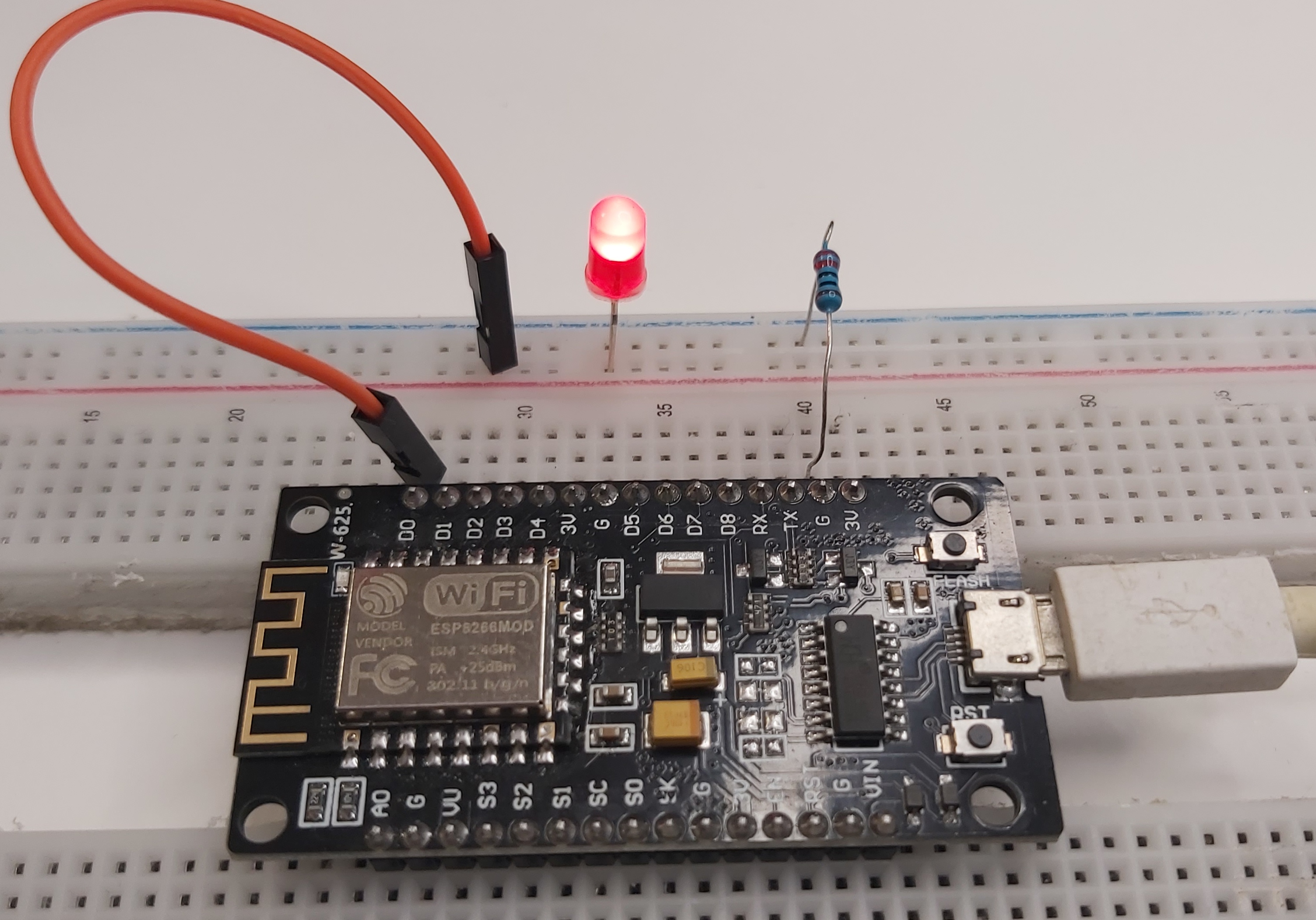
We will control the LED with a button, sending a signal from the server, which will be received by the microcontroller via the Wi-Fi channel it is connected to. Let's see the process in action:
Controlling the load
To control an AC load, we will need an electromechanical relay, which we will control using the ESP8266 microcontroller. Let's consider the connection scheme based on the SRD-05VDC-SL-C relay.
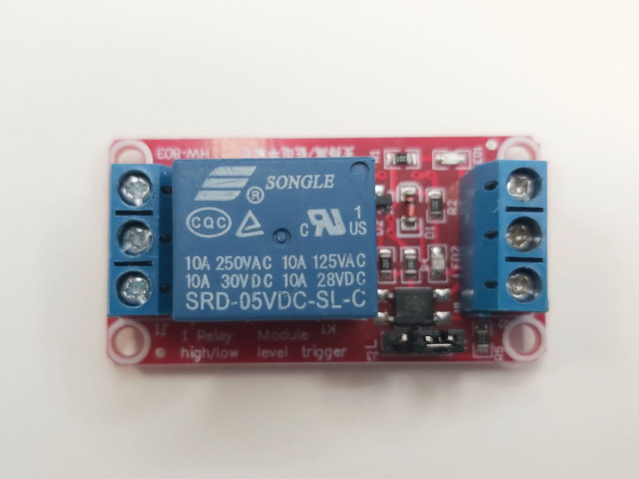
- Connect the DC+ pin on the relay to the 3V pin of the microcontroller
- Connect the DC- pin on the relay to the G pin of the microcontroller
- Connect the IN pin on the relay to the D0 pin of the microcontroller
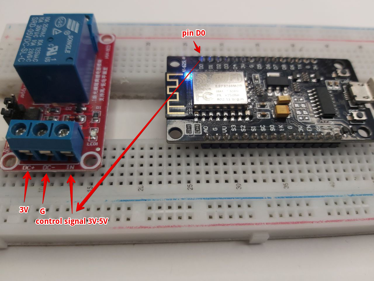
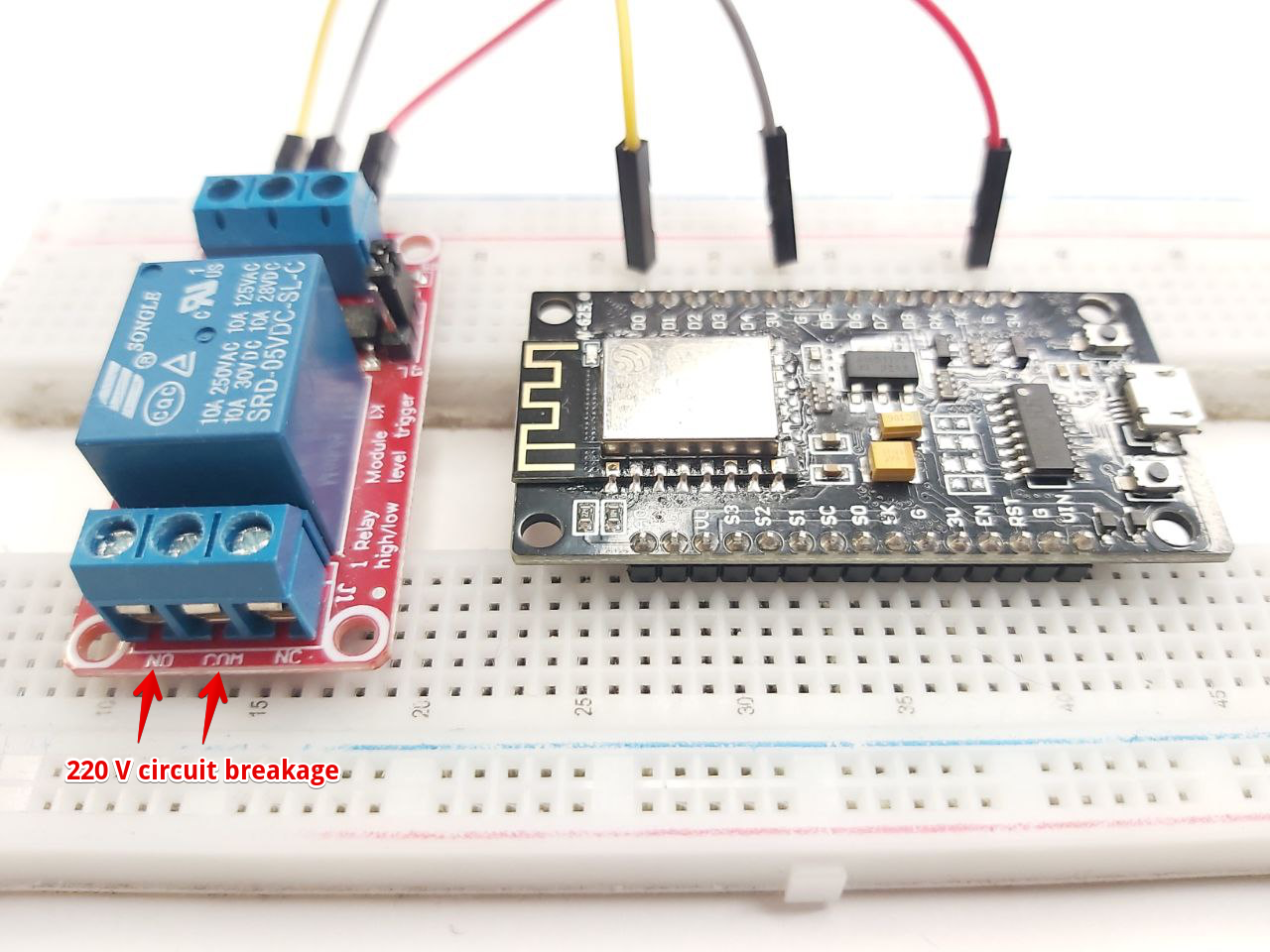
Upload the sketch to the ESP8266 module, open the panel with widgets, and using the known switch, send a 3V control signal to pin D0, which will close the broken 220V circuit and turn on the lamp. We saw how this works in the video at the beginning of the article.
Conclusion
Now that you are familiar with the basics, you are ready to start creating your own remote control project using ESP8266. If you have any questions or difficulties, refer to our guide or contact VizIot support.